BBC Model B DIY 32K Sideways RAM, for
under a Fiver
Here's a quick guide on how to fit 32K Sideways
RAM, and give yourself 7 Sideways ROM Banks, for less than a Fiver. You'll need
good soldering skills, and confidence in cutting tracks on your beloved Beeb -
don't try this if you're not completely happy taking the risk! This is just a
guide, feel free to eMail me if you get into difficulty, but don't blame me if
it all goes wrong! It works for me, so it should work for you too!
This proceedure is the same for Issue 4 and 7
PCBs. For Issue 3, the decoupling capacitor for IC101 needs to be removed.
Click on any image to get a larger picture.
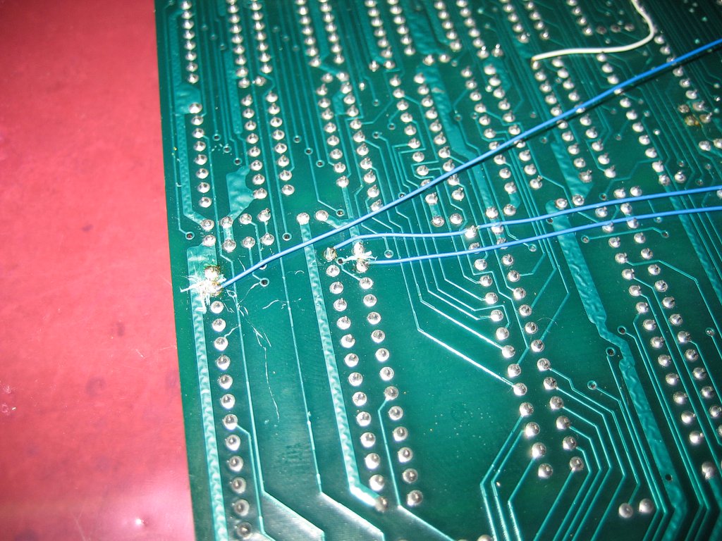
Remember when looking underneath the PCB, the pin numbers are mirrored, so pin 1
is now on the right, and pin 28 for example is on the left.
 |
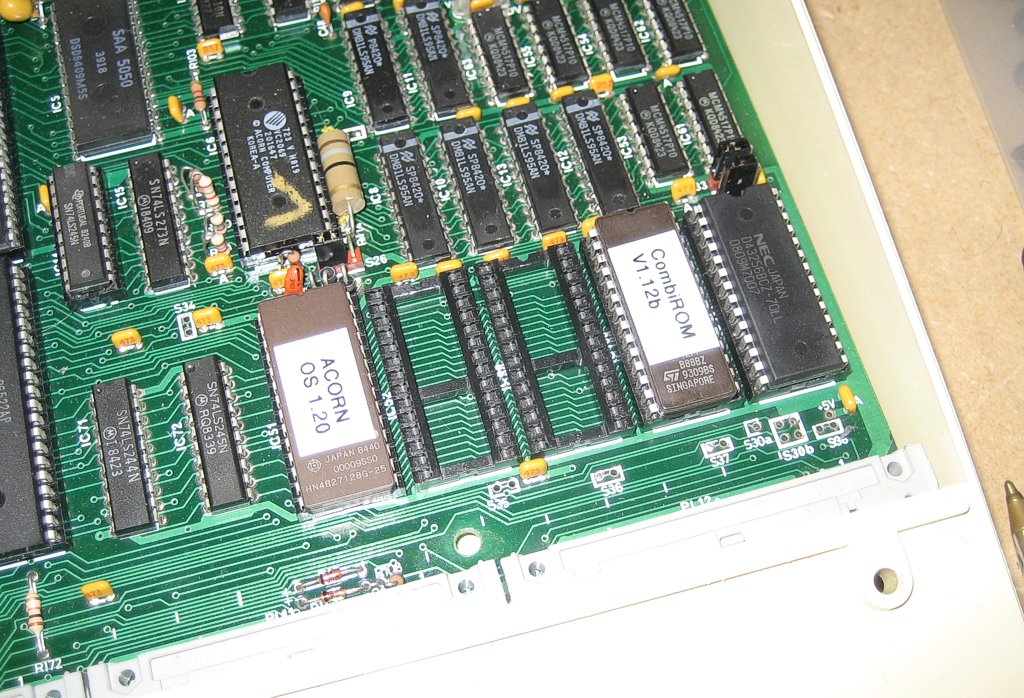
Okay, take the PCB out and lay it on a flat surface,
preferably static conductive. Here we're looking at the ROM sockets near
the Tube Connector. Take all the ROMs out of their sockets before
starting. |
 |
Grab your Stanley knife, and make sure the tip of the
blade is sharp. With a steady hand, you need to break the connection
between pins 27 and 28 on ICs 100 and 101. IC 100 should be easy, as
it's a straight cut, IC101 is a bit trickier, as it's a right angle cut.
Use a meter to make sure pins 27 and 28 are no longer shorted. |
 |
You now need some hookup wire. I use 30awg Kynar Wire from
Farnell (143-379), but you can use any thin wire you have around. Solder
one wire to pin 27 of IC 100, a second to pin 27 of IC 101, and a third
that connects pin 1 of both sockets together. |
 |
Those wires then need to be hooked up across the PCB. Pin
27 of IC 101 is the Write Strobe for the RAM, and connects to pin 8 of
IC77. Pin 27 of IC100 is Bit 3 of the ROM select latch, and connects to
Pin 11 of IC76. The wire connecting pins 1 of both IC100 and IC101 are Bit 2 of the ROM select Latch, and
connect to Pin 12 of IC76. |
 |
Once done, double check your work, and fit a 62256, 43256
or equivalent RAM in Socket IC 101. You can then plug regular ROMs in
the other 3 sockets. However, you've also modified socket IC 100 to take
upto 4 ROM images in a 27512 ROM - if you have a programmer, so you can
put things like BASIC, DFS, ADFS, VIEW etc all into one ROM, and leave
the other 2 sockets free. |
The SWR can be written to using the SRAM functions of the
Acorn 1770 DFS. You can't simply *LOAD into the RAM, as there are 2 banks and
are selected in a similar way to those on the Master. Alternatively you can
write a machine code program to load the RAM, just remember to store either
&B or &F into &FE30 before writing to select which bank you want to
write to, and always remember to return &FE30 to what is was before you exit
the program (LDA&F4:STA&FE30).
There's no reason why you can't modify the other two sockets
with the same connections as IC 100, to give you 12 ROM image banks in 3 27512s.
The sockets remain compatible with regular 27128 and 27256.
mark@retroclinic.com